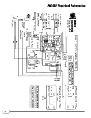
hayward pro logic wiring diagram
33 2 Speed Spa Pump Wiring Diagram - Wiring Diagram. Frequently Asked Questions.

Aqua Logic Automation And Chlorination Installation Hayward
Light hayward pool replacement spa duralite wire lights fixture logic pro wiring 12v inyopools.

. Hayward Pro Logic Wiring Diagram Hayward Wiring Diagram and also sullair 10b wiring diagram. Sullair 10b wiring diagram. Hayward wiring logic pro diagram omnilogic install breaker input vsp schematron.
Automate up to 8 rotating valves 4 or 8. Page 19 Fusible Link Hayward Heaters Refer to the instructions in the heater manual for 2-wire Remote Thermostat operation under Remote Control Connections and the diagram on the. Hayward Pro Logic Wiring Diagram.
Hayward Aql-p-4 Circuit Board Failed Replaced With Glx. Manage up to 16 pieces of equipment 4 8 or 16 Relays two heaters and a solar system on any pool spa or poolspa with shared or dual equipment. Hayward AquaPlus ProLogic Main PCB - All Date CodeVersions - GLX-PCB.
Step 3 Remove the three blue screws that secure the cover. How To Wire A 2-Speed 230V Motor to a Hayward Pro Logic System How to Wire. Hayward logic wiring inyopools 115v.
Hayward Aquarite Change 220 To 110 Wiring Diagram. Support Center Parts Diagram Library. To reduce the risk of electric shock this terminal must be.
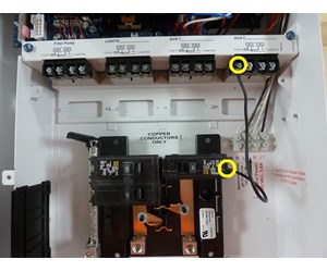
Hayward wiring logic pro diagram omnilogic install breaker input vsp. Prepare the pool water page 5. A green colored terminal marked Grounding is located inside the wiring compartment.
13 Pictures about Hayward Wiring Diagram - Wiring Diagram. ColorLogic Installation Guide - Royal Swimming Pools. Hayward logic pro wiring diagram wire pump equipment 115v explain guide describe connect ground should where inyopools booster.
Close US English. USE ONLY HAYWARD GENUINE REPLACEMENT PARTS 4 Installation Steps Details on each installation step are presented on the following pages. Hayward wiring logic pro diagram omnilogic install input breaker vsp schematron.
The Hayward Pro Logic is a multifunction pool controller used to fully manage your poolspa system. Step 2 Open the door to the Pro Logic box. Wiring diagram intermatic control freeze protection circuit switch pool electrical mechanism basic hp volt spa gfci aquapoolstore equipment 240volts 3hp.
11 Pictures about Hayward AquaPlus ProLogic Main PCB - All Date CodeVersions - GLX-PCB. A green colored terminal marked Earth Ground is located inside the wiring compartment. See All Steps Step by Step Step 1 Turn off the power to the Pro Logic at the main breaker.
Hayward aqua rite salt logic pro diagram wiring aquarite pool troubleshoot inyopools generator diagnostics troubleshooting chlorinators. The Pro Logic can control pumps valves lighting heaters and chlorination. Hayward Wiring Diagram - Wiring Diagram.
9 Images about sullair 10b wiring diagram. To reduce the risk of electric shock this terminal must be connected to the grounding means.

Repair Your Hayward Goldline Aqua Logic Glx Pcb Pro System Board 761418010523 Ebay

Diy Replacement Of Old Goldline Pcb W New Hayward Replacement Due To Comm Error From Cpu R Pools
How To Wire 115v Equipment To The Hayward Pro Logic Inyopools Com

Hayward Aql P 4 Circuit Board Failed Replaced With Glx Pcb Pro Hayward Pro Logic Support
Generic Install Manual4

Hayward Pro Logic Support And Manuals

Hayward Pro Logic Installation Manual Pdf Download Manualslib

Procedure Pour Retirer Et Reinstaller Le Board D Un Hayward Pro Logic Aqua Logic By Reparation Chlorinateur Marques Hayward Et Jacuzzi Facebook
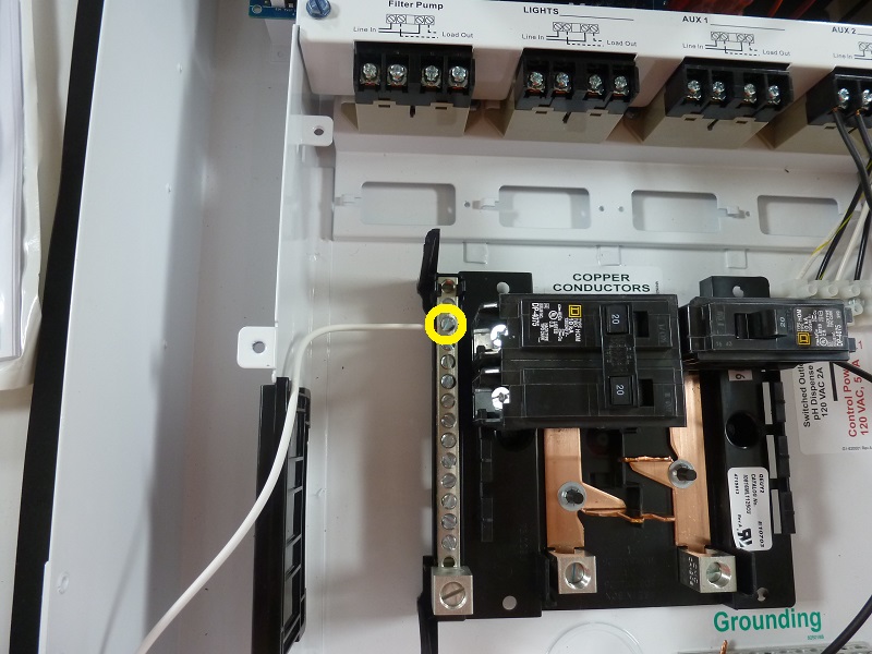
How To Wire 115v Equipment To The Hayward Pro Logic Inyopools Com

Repairing My Aqua Rite Pcb Glx Pcb Rite That Was Damaged By Lightning Russ Do It Yourself Home Workshop
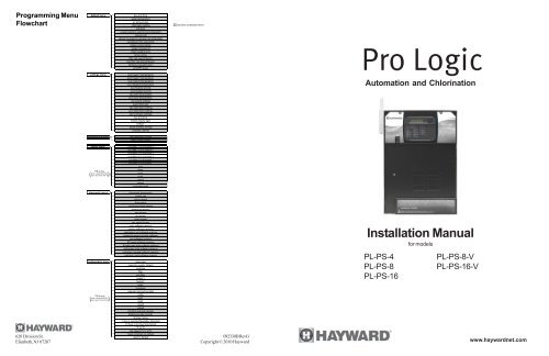
Pro Logic Installation Manual Hayward

Hauskraftwerk Autarke Energieversorgung

Hayward Aqualogic Prologic Automation Share Your Projects Home Assistant Community

How To Wire A Hayward Aquarite On 115v Youtube
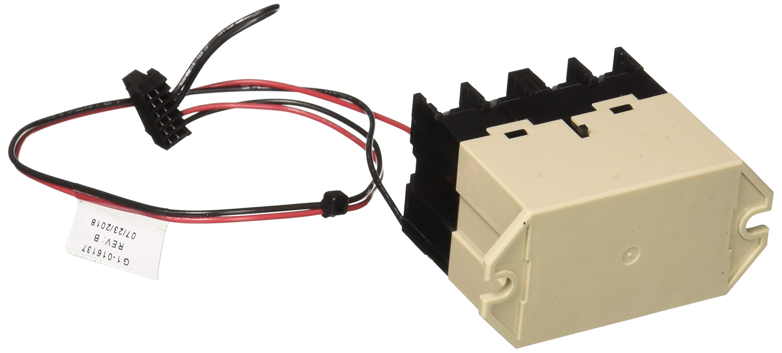
Amazon Com Hayward Hlrelay Omnilogic44 1 Relay Module Patio Lawn Garden

Repairing My Aqua Rite Pcb Glx Pcb Rite That Was Damaged By Lightning Russ Do It Yourself Home Workshop
Hayward Pool Automation Wiring Location Any Idea Which Is The Correct Location For The Serial Bus Here R Homeautomation