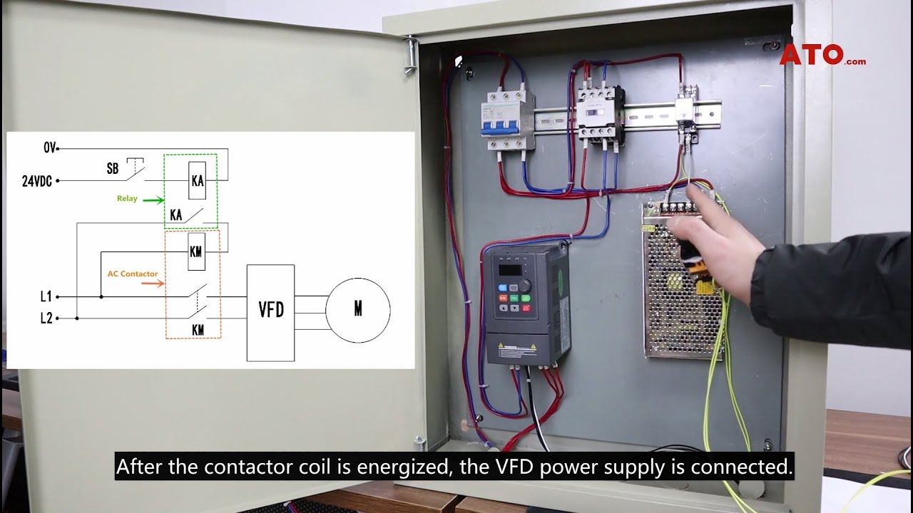
vfd wiring diagram
Wiring diagram shows a pictorial view of the components such that it resembles its electrical connection arrangement and position in real circuit. Incorrect VFD terminal wiring could result in VFD andor equipment damage.

Pin On Electrical Engineering
In this tutorial we will learn about Autotransformers.

. Except as noted in the table below an IO_x_IN pin can always be used to provide a digital input eg. 266 vs 453 is a no brainer. RepRapFirmware 3 can be configured to map these ports to the appropriate functions as required.
Your authorized Frick representative should be consulted for their expert. MAN - Repair manuals Wiring Diagrams Fault codes. The circuit will perform the same as a hard wired electrical circuit.
Prepare a Control and Power drawing. The manual says the polarity of 12 doesnt matter. They are mostly used for wiring installation in home and industries.
The design can be edited and re-tested saving valuable time when it comes to hard. Apr 17 2017 Diy powder coating oven wiring diagram a beginner s overview of circuit diagrams. Control panels communications specifications and wiring diagrams see publication series 090040O 090040M 090040CS and 090040SPC.
For endstop inputs or filament monitors and an IO_x_OUT pin can always be used to provide a digital output. This is a complete guide to theory and design of Autotransformer its efficiency numbers electrical symbols starting technique protection measures advantages disadvantages applications and many more. Going with a timer relay and contactors for pony motor and idler.
Soft Starter Its Circuit Diagram Operation Advantages Applications Our industries use various kinds of machines. Other names for a VFD are variable speed drive adjustable speed drive adjustable frequency drive AC drive microdrive and inverter. Commissioning and Parameters Programming in VFD.
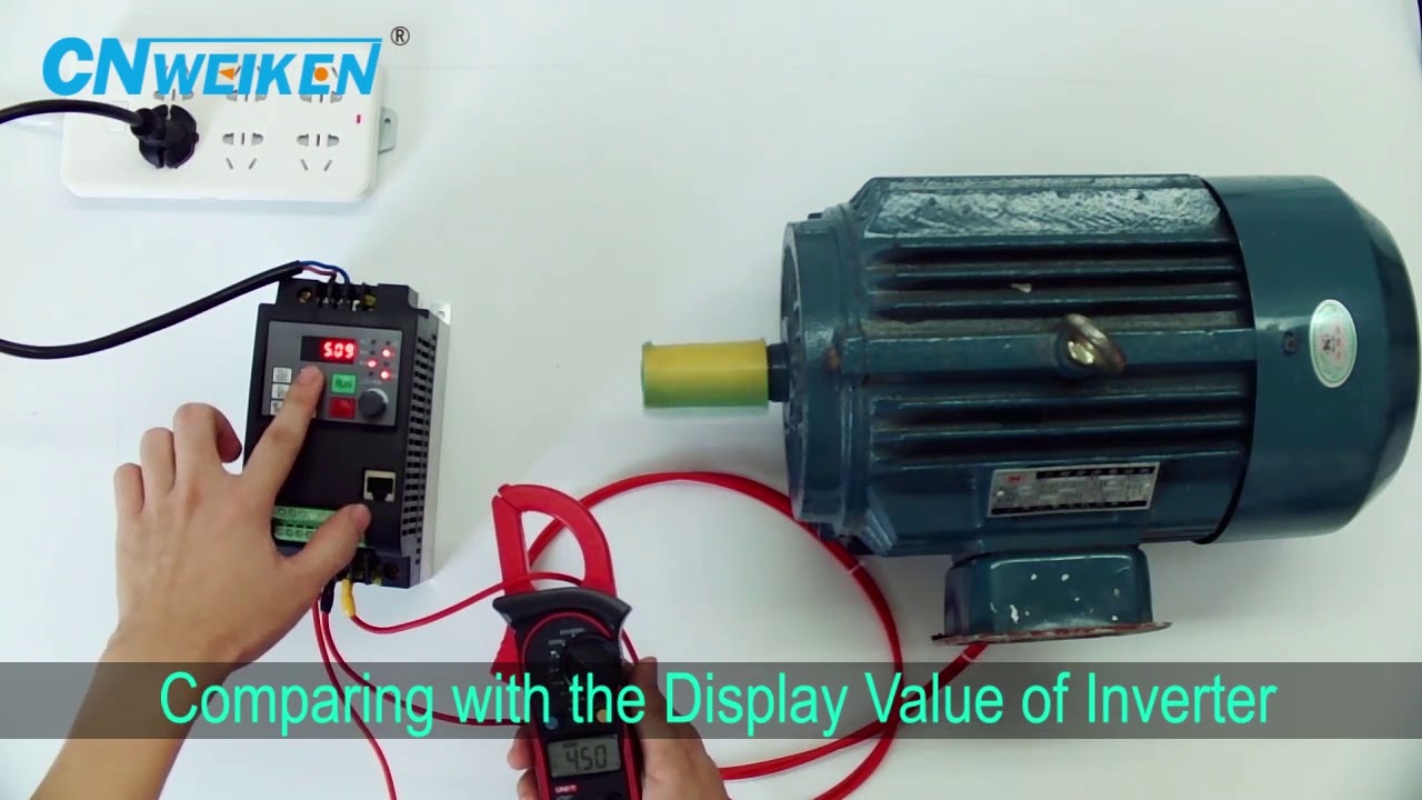
Frequency or hertz is directly related to the motors speed RPMs. It is most important that these units be properly applied to an adequately controlled refrigeration system. If you have 0-1000 at RC rate 1.
This is a complete tutorial about PLC ladder logic to control variable frequency drive VFD for motor speed control with speed selection from Field Local Panel or SCADA graphics. It really helps in showing the interconnections in different equipment such as electrical panel and distribution boxes etc. T he Constructor program makes the creation testing trouble-shooting teaching and printing of electrical ladder diagrams diagram schematics electrical wiring diagrams electrical drawings and one line diagrams fast and easy.
1 phase pony motor 2 HP TEFC is like 266 and 3 phase is 203 and dont forget the need for 250 VFD. Prepare a PLC program. The induction machine is one of the most used three phase AC machine which is almost 70 of the motors used in industries.
The input power phase sequence does not affect a direction of motor rotation. The phase sequence on VFD terminals U V W to motor will affect the direction of motor rotation. A Variable Frequency Drive VFD is a type of motor controller that drives an electric motor by varying the frequency and voltage supplied to the electric motor.
Their robust construction and high efficiency makes it the best choice for every industrial sector. Reversing the polarity - of the digital control terminals can damage VFD. So below are pictures of my wiring diagram PID settings and PID instructions.
Totally new and revamped idea here.

G540 Spindle And Relay Wiring Diagram Diagram Electrical Diagram Wire

77 Unique Reversing Starter Wiring Diagram Circuit Diagram Electrical Circuit Diagram Electrical Diagram

The Post Explains A Simple Variable Frequency Drive Or Vfd Circuit Which Can Be Used For Circuit Diagram Electronic Circuit Projects Electrical Wiring Diagram

Delta Vfd Programming How To Set Parameter External Switch Potentiometer Youtube External Delta Switch

Variable Frequency Drive Circuit Diagram Circuit Diagram Circuit Knowledge

Inverter Standard Wiring Diagram T Power Diagram Control

Vfd Panel Paneling Block Diagram Inductors

What Is Ac Drive Working Types Of Electrical Drives Vfd Electrical Circuit Diagram Electrical Diagram Diagram

The Post Explains A Simple Variable Frequency Drive Or Vfd Circuit Which Can Be Used For Driving All Circuit Diagram Electronic Engineering Electronics Circuit

Single Phase Vfd Circuit Using Full Bridge Driver Electronic Schematics Electronics Circuit Circuit

Rituo Vfd Inverter Drive Hook Up To Spindle Motor Wiring Guide Diagram Cnc Router Router Hook

Variable Frequency Drive Vfd System Need Working Benefits Arduino Projects Simple Arduino Projects Arduino

3 Phase Induction Motor Control Using Variable Frequency Drive Vfd Elex Focus Electrical Circuit Diagram Circuit Components Circuit Diagram

The Post Explains A Simple Variable Frequency Drive Or Vfd Circuit Which Can Be Used For Driving All Circuit Diagram Electronic Engineering Electronics Circuit
How To Control Vfd With Push Button Switch Terminal Control Wire Control Youtube Electrical Circuit Diagram Control Wire

Ac Dc Drive Vfd Control Terminal Wiring Diagram And Concept ह द म Youtu Mechanical Engineering Design Electrical Circuit Diagram Engineering Design

مهندس محمدیان 09132211861 تعمیرات اینورتر اینورتور درایو 3vf Vvvf Vfd Vsd Abb Acs350 Wiring Di Circuit Diagram Electrical Connection Electrical Wiring
What Is Vfd Variable Frequency Drive Hindi Driving Variables Hindi
Pin On Frequency Inverter